 Nico Brailovsky's thought repository
New project: playing with ESP32s
Post by Nico Brailovsky @ 2026-05-21 | Permalink | Leave a comment
I spent about 15 minutes not knowing what to do with my life after I finished my last project, then opened up my box of ESP32s and decided to start a new one. This time I'm building a presence sensor.
When I sit down to watch TV, I need to configure the lights in the correct way (there is a correct way), the audio profile, the TV input, even the correct heating settings. I can do all of that from my phone, or even better, from a Zigbee button, but I decided that's still too much work and it should all happen automatically. When I sit down to watch TV, everything should automatically be set up the way I like it. Because I don't live alone, when my wife sits down to watch TV it should be set up the way she likes it. How hard could that be?
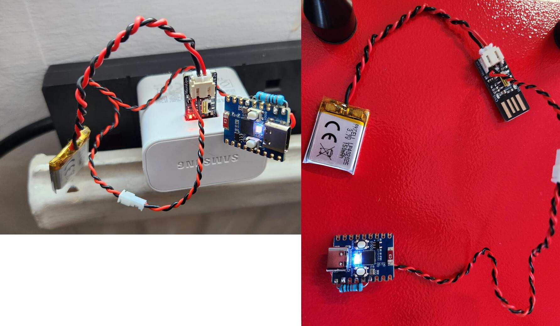
Started with a few basic components: a battery, a USB/LiPo charger, and the ESP32. Above, a "proof of life", showing that I can flash an LED from either battery power, or from USB power. I found later that buying an ESP with battery management is actually cheaper than buying an ESP+battery manager, but I already have these components and I'm not planning to waste them. Since I can flash an LED, surely that's enough to work on the industrial design of my new sensor.
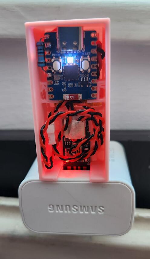
Now that I have a 3D printer, nothing can stop my mad ID skills. Except a few mm of bad alignment in my 3D printer. I'm not too unhappy with the results, though, and here's version P0 of my presence sensor:
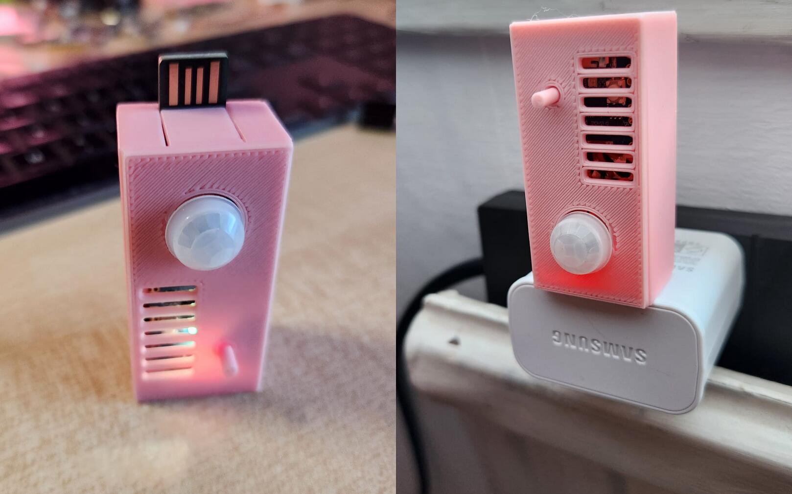
The assembly here looks pretty but the picture is a bit of a lie, as the sensor doesn't do much yet. The firmware is in its early stages, although it can already connect to an MQTT server and broadcast its battery status. The idea is to pair my phone over Bluetooth, and then use it as an identification mechanism, plus the PIR sensor to wake up the device (did I mention the battery is tiny?).
I don't know how useful this sensor will be: the battery seems quite small, and I haven't done any power measurements yet to estimate the lifetime of the device between charges. For now, it's been a good experiment to learn to use my 3D printer, and to start planning V2 of this sensor.
As for the identification part: I managed to coax my phone into automatically connecting to my sensor by declaring the Bluetooth interface as an input device, and the identification part seems to work remarkably well: by reducing the TX power of the ESP, I can get a useful radius of about 3 or 4 meters, enough to put one of these in a room and know who is in there. I can't wait to find out what this device will do once both me and my wife sit down to watch a movie together!
Homeboard: Complete
Post by Nico Brailovsky @ 2026-05-09 | Permalink | Leave a comment
This is an extremely rare occurrence: I have finished a project!
I have now completed my Homeboard project. This doesn't mean there are no bugs (although tactical systemd unit restarts take care of most known bugs), and it doesn't mean I won't ever build new features (some day I'll make it boot over LAN). It does mean I achieved all of the initial objectives I had for this project (or have, at least, clever workarounds for missing features). It is now complete and stable enough that I don't feel too ashamed of calling it done. Of course, the project is also built in an extensible way so that I can add new (software!) features cheaply.
Looking back:
- The project took 2 years to complete
- The feature I'm sad about not achieving: buttons! Having a physical interface to interact with the device is nice, but the cables in my assembly proved too fiddly to work reliably. I did add a QR code to the display to quickly open the web remote control, however, so I can live without it.
- The feature I'm most proud of: SVG overlays. This was a pretty brilliant idea, if I may say so myself. Running on a Raspberry Pi Zero over PoE, the device is very compute-constrained. This means no fancy HTML or React rendering. Using SVG, I can still overlay arbitrary data and easily extend it, while keeping the device software lightweight enough the platform.
- The best bug: a bad mmWave sensor placement. It picked up occupancy signals from the display, meaning the panel would be in an on/off loop.
You can build your own, extensive instructions are available in the project's repo.
Homeboard v2
Post by Nico Brailovsky @ 2026-04-23 | Permalink | Leave a comment
This week I decided to revive my oldest homeboard, one that suffered a bit of unplanned refactoring after a rapid encounter with the floor (about a year ago, now. Turns out I don't quite have enough time for all of my side projects, or I have too many side projects for my free time). Of course, it wasn't really a repair as much as a complete re-do, salvaging a few pieces here and there.
Side note: xkcd 3233 feels very autobiographical, and on topic for my homeboard series.
Electrical changes
While the brains (a Raspberry Pi Zero), the display and the panel controller haven't changed, I found that this homeboard was rather unstable under load (when decoding and rendering a jpeg to screen). This would cause a brownout and the display to shut off for a second, which was quite jarring for a device meant to show pictures. Worse, sometimes this would happen on startup, making it enter a display restart loop (surprisingly, the RPI survived the brownouts).
The brownouts were probably caused by aging components in the boost converter that switched the 5v from the PoE output to 12v for the display controller, eating any margin for power consumption peaks. I changed this to use a 12V PoE output to feed the display, and then a 5V step down for the Pi. I don't know if it's just newer components or a simpler setup (step down is easier than boosting up), but the build was a lot more stable. The Pi is now fed through GPIO, which is limited in current compared to USB. That's probably a good thing, considering my PoE is limited to 12W anyway.
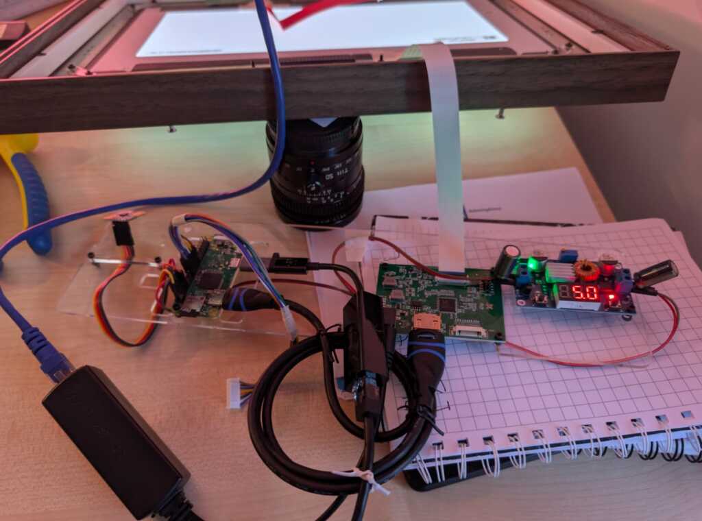
Though going from PoE->Pi->Display to PoE->Display->Pi made my system more stable, there were still transient drops in voltage and, rarely, brownouts causing the display to go off. I don't have any fancy measurement equipment, but I know the system is running at the power limit of my PoE adapter (around 12W), so I added a couple of 1000uF capacitors to handle the transients. 1000 was just a guess based on power usage and assuming a 10ms transient, which seemed reasonable to a layman in this area. This took care of any stability issues, and the system has been rock steady since.
"Industrial design" changes
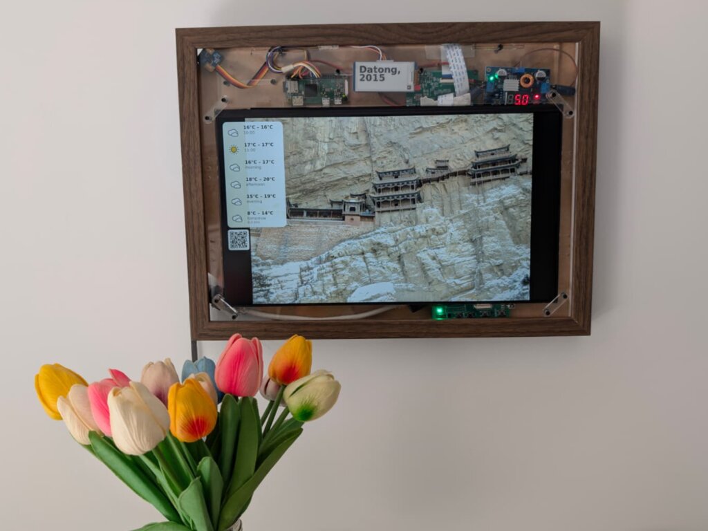
The new 12v PoE is smaller than my old 5v PoE, so I was able to reuse the old slot that housed it to put the mmWave sensor. This had been a source of hardware bugs before, and the new position lets me keep the sensor isolated from any electrical interference. I'm especially happy about this, as it means that while building this I learnt at least one thing.
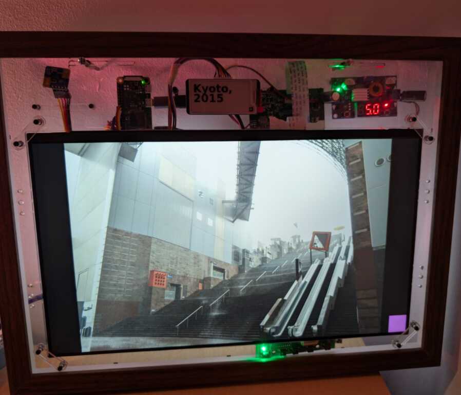
The new version also incorporates a clip holder for the eink at the front, so now it's not floating around. It sticks to the (transparent) front pane and acts as a metadata display (here, year + city for the photo being displayed). I found the font needs to be quite large to be useful, which indicates that the screen is too small (about 3'') or that I am too old (both?).
Finally: sooo much tape. For this iteration, I tried to tape down anything that moved, to minimize cables breaking free and escaping. It helps, none of the fragile connection points move, but the end result is as if a mummy had assembled my homeboard. I bet if you are an industrial designer reading this note, you're crying right now. Ragemail welcome (ideally with suggestions to improve the design, too).
Not fixed in this version: there still isn't a good way to hang the frame. It hangs precariously from the wooden edge, without a notch to keep it in place. I was hoping the mount for the boards would double as a wall mount, too, but it's not sturdy enough to hold the weight.
Software changes
Software changes have been massive, but of course less visible than hardware changes. While I still need to update the repo, the new Homeboard doesn't use Wayland anymore. The system now uses DRM, with no compositor on top. This makes startup much faster - quite unnecessary for an appliance that restarts maybe once a year, but the architecture "feels" nicer. It also got split from one monolithic app into a set of services that interface over D-Bus. Perfect for LLMs to dig around and change the project. The software layer now is
- the main "ambience" service (showing pictures, announcements, driving the eink display, etc),
- an occupancy service, that announces if anyone is around to see the pictures,
- a DRM service, that owns the display management,
- a picture service, that provides photos to the ambience service (by grabbing them from wwwslide),
- a D-Bus to MQTT bridge, enabling reporting and remote control of the device.
The new Homeboard software has working eink integration, so I can see picture metadata at a glance, and I finally implemented a UART interface to the mmWave sensor, with quite a lot of AI help to reverse engineer the protocol. I can now calibrate the sensor, which gives much better occupancy results. Moving the sensor to a D-Bus service also means I can replace it with a newer model, whenever I want to (quite likely never).
Finally, the Homeboard is now integrated with my custom home automation service, ZMW. This gives me a few new features, such as using the mmWave sensor in the homeboard as a presence sensor for home automation, controlling the slideshow from a Zigbee button, and using the display to announce things or show useful information, such as the price of cat food in today's spot market.
End result
One final complication: after (re)building this new homeboard, I ended with 90% of the parts I need to build a 3rd Homeboard. Should I?
Training a new TTS Voice
Post by Nico Brailovsky @ 2026-04-01 | Permalink | Leave a comment
Just to avoid renaming my blog to "Weekend projects", I actually did this one over the week. My home automation system runs a text-to-speech service, based on Piper. I wasn't entirely happy with the voices that I had, so I decided to train a new one. This turned out to be a fairly involved (even if not very hard) process, so I put some notes for the next time I need to do this, which I'll copy here too because no one charges me for byte stored:
Training a Custom Piper TTS Voice
This project uses Piper as its TTS engine. Piper works great as a real-time(ish) TTS engine for Raspberry Pis. Other engines (Coqui, F5-TTS, Kokoro) offer better quality or style control, but aren't real time in this compute envelope. Training new voices for Piper is not hard, although there are many, many, steps required.
Literature claims about 1 hour of audio is needed to fine-tune an existing model (ie give it a new voice). Training from scratch is 10x that. The recordings need to be, of course, high quality, with no reverb, echo or noise, all from the same voice. For Piper, the training format is 22050 Hz S16 mono. If you want your new voice to sound in a specific way (eg angry), then make sure your training data is... angry.
Training data
You will need to provide training data as individual files, plus a CSV that references the wav file + the text. Something like
wavs/001|This is the first sentence.
wavs/002|Here is another sentence.
Of course, it's unlikely you'll record (or find) an hour of audio in this format. Instead, and much more likely, you'll end up with a single long recording which then can be chopped up in more manageable pieces. For this,
apt-get install ffmpegpip install -U openai-whisper [--break-system-packages]- If needed, pre-preprocess your input (use Audacity to downmix to mono, cut unnecessarily long silences, etc)
- Run the prep dataset script
The script uses Whisper to transcribe and get timestamps from the big wav file, and then chop it up into smaller ones. You should end up with two CSV files, one for "high confidence" sentences and one for the utterances where the model wasn't quite able to transcribe or find a clean sentence boundary.
[Tip: if you're getting your material from an online source, do pw-record out.wav and use qpwgraph as a patch bay to route to a wav file]
Training
The training READMEs of both the old, archived, Piper project, and the new forked Piper project include training docs. I found I needed to read both to build this training guide.
We're not training from scratch, so pick a checkpoint in HuggingFace. If you'll train an English voice, pick an en model - the closest one you can find to your target voice.
Once you have your checkpoint and training data,
sudo apt-get install python3-dev cmake build-essential python3-scikit-build-coregit clone https://github.com/OHF-voice/piper1-gpl.git- Create a venv (we'll install a ton of Python packages):
cd piper1-gpl && python3 -m venv .venv source .venv/bin/activatepython3 -m pip install -e '.[train]'./build_monotonic_align.shpip install scikit-build-corepip install scikit-buildpip install tensorboardIf you want to monitor progress (you do)python3 setup.py build_ext --inplace
At this point, you should have an environment ready for training, which I trigger with
python3 -m piper.train fit \
  --data.voice_name "Nico" \
  --data.csv_path metadata.csv \
  --data.audio_dir $WAVs \
  --model.sample_rate 22050 \
  --data.espeak_voice "es-AR" \
  --data.cache_dir ./cache \
  --data.config_path '$COPY_OF_CHECKPOINTS_config.json' \
  --data.batch_size 22 \
  --data.num_workers 8 \
  --trainer.precision 16-mixed \
  --ckpt_path '$PATH_TO_CHECKPOINT'
I would be surprised if this works out of the box, however. A few things I needed to fiddle with to get this running:
- Module names: some manuals say
python3 -m piper.train, others saypython3 -m piper_train.fit. You may need to read some code to find out which one you need. - Model mismatches; I downloaded a high quality checkpoint but was trying to train a mid quality model. This will error out with Torch complaining of architecture mismatches (I fixed by downloading a mid quality model)
- Metadata CSV format may be wrong, it may or may not want the file extension in the CSV file
- OOMs, of course. You'll need to play with batch_size and num_workers to fit your training system (You aren't training in your target, right?)
- Piper refused to load the checkpoint due to Torch version differences. My LLM provided a script to hack an existing checkpoint into something that Piper liked.
Finish Training
While training, you can run tensorboard --logdir ./training/lightning_logs, this will create a web UI with information on training progress, and a few audio samples you can listen to. You can stop training once the loss stops going down for a few epochs, or when the audio samples start sounding good enough. The manual claims there is a way to test with arbitrary sentences while training, however, I couldn't make it work.
For reference, in a system with an I7 10th gen + RT2080 (8GB) training was done in about 20 minutes, maybe less. In an old i7 6th gen and 16 GB RAM (no GPU) training would complete after the heat death of the universe.
Once done, you can export your model with python3 -m piper_train.export_onnx /path/to/model.ckpt /path/to/model.onnx and cp /path/to/training_dir/config.json /path/to/model.onnx.json
Linklist
- Checkpoints for fine-tuning in HuggingFace
- Other person's notes on training Piper
- Old Piper training docs
- New Piper training docs
Alternative engines:
- Kokoro: better quality and style control, but not real time on a Pi
- F5-TTS: better quality and style control, but not real time anywhere. Needs a GPU.
Weekend project: Nanny Godmin
Post by Nico Brailovsky @ 2026-03-15 | Permalink | Leave a comment
Another (multi)weekend project: Nanny Godmin is a service to monitor (and remotely lock) Android devices. It's not meant to work against adversarial users, it's meant to limit kids' device usage time, and set the devices' volume.
As much as I'd prefer to let children self-regulate usage, I find that encouragement through some form of monitoring is needed. I also find myself getting lost in my own weekend projects (ahem, this one), which at times leaves me without a reminder that I need to... discourage device utilization. This service is now reminding me, as well as my children, when it's time to put our devices down.
Fun anecdote: I set the usage threshold fairly low, for testing purposes, and forgot about it. Went about my day, and discovered my phone was locked when I tried to use it for a payment. I have, since then, implemented a mechanism to fail open or closed when the service is unreachable (that is, when I'm outside my LAN), but in at least one occasion, I have now locked myself out of my own device.
From the readme:
NannyGodmin is a parental control/remote management and monitoring Android service. It is designed to run as a persistent foreground service, track user activity, capture screenshots remotely, and allow a remote server to "lock" the device or adjust system settings. It's not meant to be used as an MDM (for starters, there is no attestation), it's meant to be used as a remote control for devices in a known safe security domain (ie only use it in your LAN), with non adversarial users.
Lock/unlock all devices, manually, or automatically based on usage thresholds or on a timer
Remotely set devices' volume
Request devices' screenshots
Get a usage report to monitor when the device was active each day, and how long it was used for
Get a list of used apps, and for how long they were active

Some day I'll extend this with a proper attestation mechanism and true MDM owner mode, mostly because I want to understand how hard it is to build an MDM system. For now, it's a good app to control the volume of devices at home without needing to shout to anyone!
Weekend project: Raspberry Pi CRT
Post by Nico Brailovsky @ 2026-02-22 | Permalink | Leave a comment
In what may be the most useless project I've done in a long time, I spent the weekend making an old CRT work with my Raspberry Pi.
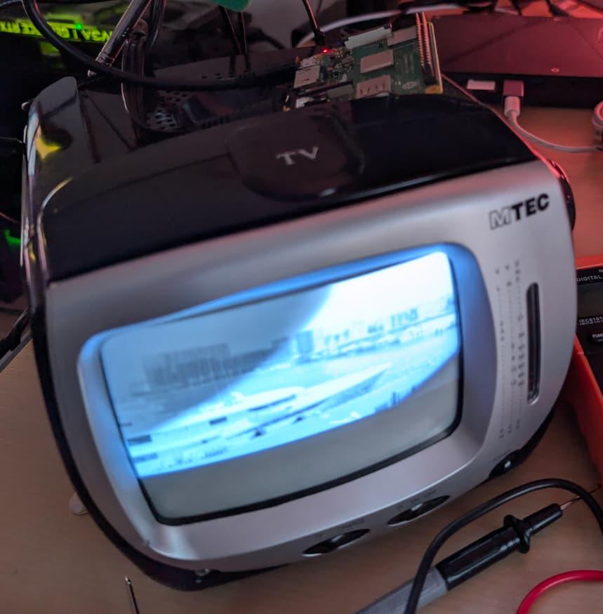
I don't think there will be much use for this project. Ignoring that this is a CRT (720x576 black-and-white), the TV I picked up is pretty noisy. I don't miss the high pitched whine of a CRT (mine is 11 KHz, if you're wondering). Still it was fun to make this work, and I did learn a few things:
- The Raspberry Pi has an SDTV composite/RCA video output. It's shared with the audio output jack. The audio out supports pins with 4 connectors (TRRS connector), and you can get video in one of them.
- There are, of course, multiple standards for TRRS. A Pi uses TRRS CTIA, in which each connector of the pin is (tip to cable) left audio, right audio, video and ground. Unfortunately, many vendors don't specify which standard you're getting. If you get the wrong one, it's not complicated to rejig the cable to be CTIA, just a few snips and some soldering.
- A lot of articles online will tell you that adding
sdtv_modeto /boot/firmware/config.txt is enough to enable video out. I found that's not the case, you'll need to specify alsosdtv_aspect,enable_tvoutanddtoverlay=vc4-fkms-v3d(this last one enables firmware control of video out. I didn't dig into why this is needed, and KMS doesn't work). - You will also need to pin the core frequency. Frequency scaling will affect video rendering.
I put all these setup steps in a convenient script, available as part of the app I'm using to show pictures. Now I need to think what I can do with this ridiculously large piece of ancient tech, which has less resolution than my watch.
Weekend project: Tripmon
Post by Nico Brailovsky @ 2026-02-08 | Permalink | Leave a comment
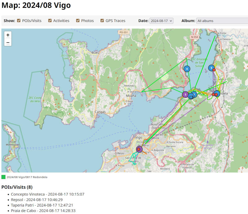
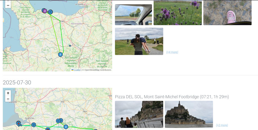
Tripmon is a way to visualize my trips (and daytrips).
I have (had?) a lot of data in gmaps and no good way to visualize, or merge, with my extensive album collection. So I built a small service to categorize pictures and merge them with map traces. The service will also try to score the "best" pictures, for whatever definition of "best" a few ML models choose, and display just a few highlights for each part of the trip.
This project falls, for the most part, in type 3 of my AI categorizaion: largely vibe-coded, and if it breaks I wouldn't know why. This is in contrast with other weekend projects; I also spent some time adding voice control to my home automation system. I "care" about the code in my home automation system, but I don't care much about the code of my Tripmon project. Adding new features to my home automation system takes 10x the time it takes to add new features to Tripmon, as I go through a very through review and refactor process. In my home automation service, when things break I know exactly why and how (it's fairly important for me to be able to turn my lights on or off). In Tripmon, if something doesn't work I just ask AI to iterate, until it more or less does what I want.
From the readme, Tripmon will:
- Scan a directory for photo albums, and derive day-trips from album names.
- Group day-trips into trips, then generate a "report" for each trip.
- Merge each trip with GPS traces from G Maps.
- Run an analysis on your albums, and select the best N pictures (for whatever definition of "best" the model that looks at pictures may have)
With this information, Tripmon will generate a report for each trip and day-trip. The report will include
- A map overlay with the visited locations and the transport between each
- A list of places visited, and the time spent in each place
- A list of pictures to go with each place
Weekend project: (Mini) audio science talk
Post by Nico Brailovsky @ 2026-02-03 | Permalink | Leave a comment
Another project to file under "brilliant ideas": I spent the weekend (and a bit more, really) working on a set of experiments to teach how audio works, for children.
While publishing my set of JS audio demos a few weeks back (wonder if I need to credit AI, too), I figured I should try to widen my audience beyond other software engineers. The material consists of simplified explanations of how audio transmission works, and how computers work with audio. Finding a balance between oversimplifying things and staying topic-relevant for children has been a challenge, but I'm quite happy with the final results. There are also plenty of experiments that, hopefully, will keep the session engaging.
While I doubt many 8 year olds are reading these notes, I'll be getting some feedback on this sessions soon. Wish me luck!
Raspberry Pi Karaoke Machine
Post by Nico Brailovsky @ 2026-01-24 | Permalink | Leave a comment
I had a brilliant idea to setup a karaoke machine for a party. Working with audio and computers means I always have a fresh supply of microphones, speakers and rpi's in diverse state of brokenness, so I figured it shouldn't be too hard to throw everything together and try to build a karaoke machine. It was easier than I expected, and it only took a couple of hours, so here's a guide to repeat the same process when I need it next year.
BoM:
- Rpi 4+
- A touchscreen
- A [portable] speaker with aux input
- Some USB microphones, ideally using an audio DIN connector
A touchscreen will make the system portable without too much hassle. Also, prefer wired connections in the system: you could use bluetooth mics/speakers, and your life will be simpler by doing so, but each bluetooth hop will add quite a bit of latency, up to 200ms. May not seem like much, but 200ms is the equivalent of ~70 meters: imagine if you had to shout to someone 70 meters away?
Why DIN? USB cables have a length limit, and unless you have top of the line expensive USB cables you are likely limited to 1 meter, maybe 2 (and let's be honest, if you're assembling a karaoke machine out of spare parts, how likely is it that you have a lot of expensive USB cables lying around?) A DIN mic will have a much more permissive length limit, allowing you to go for 5 or even 10 meters with a cheap cable. This makes up for the range you lost by not using bluetooth. It makes the system more cumbersome, as you need to deal with long cables, but also a lot more resilient. And if you are reading this, you probably ENJOY cable management anyway.
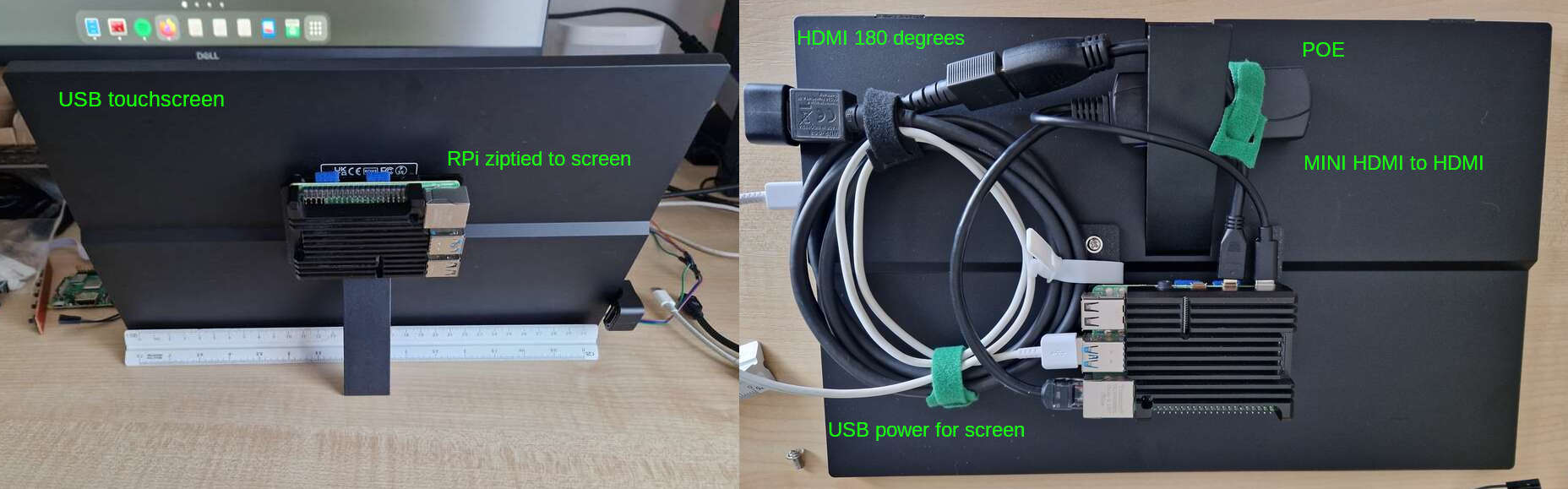
For this build, I'm reusing the beautiful industrial design of my P00 Homeboard: an RPI4 wirezipped to a touchscreen. I didn't use POE, however, as the power requirements of the USB mics + preamps go beyond what 802.3af can offer (less than 15W!).
Software
- Get your base rpi OS installed as usual
- Install PiKaraoke. While you can go for a Docker container or a pipenv, I think it's easier to
pip3 install pikaraoke --break-system-packagesand make this a system (user) package. I'll just wipe the OS for my next project anyway. - PiKaraoke will need a js runtime, the page explains how to install one. Again, easier option is to make it a system install and just wipe the OS for the next project.
- apt-get install qpwgraph: we will use this to create a mic/speaker loopback (ie the karaoke part of the system)
Runtime setup
The default rpi OS includes an on screen keyboard for touchscreens. It's cumbersome to use, but the setup is simple enough that it's just about doable. If you expect to use this as more than a temporary setup, you may want to automate the steps below to run on startup.
When starting the system, use qpwgraph to create a loop between your mic(s) and the speaker. This was a lot harder in the ALSA/pulseaudio days, but with Pipewire it's trivial. Be careful with the echo: place the speaker far enough from the mics to avoid creating a feedback loop. Maybe a future version of this system will include an echo canceller? Try it out to ensure the loopback works fine.
Run ./usr/local_bin/pikaraoke (or wherever the install put the binary). This will start the service. From there, just set up the system with your phone using the QR code it displays.
Latency
Keeping latency down is important for this build. Once you have it running, I recommend running a quick latency test. You will need a metronome (or any other thing that can produce periodic clicks, and lets you control the tempo). Get the metronome close to the mic, and put your ear close to the speaker with a volume low enough that the mic doesn't pick up echo.
With this setup, you should hear two clicks: once from the metronome, and once from the speaker, after having gone through the system. Adjust the tempo until you can hear a single click. When you do, it means that the loopback latency of the system equals the latency between clicks: the time it takes for sound to trouble from the mic, through the OS and back through the speaker, is the same as the time it takes the metronome to produce two clicks (plus some acoustic delay, which is below your ears measurement error for this setup anyway).
If your metronome is running at 120 bpm when the two clicks "merge", your system latency is around 500ms. My RPI+USB mics was around 300ish. High, but usable. For a next build, I should try to get this down to 100 or less.
Slideware engineering: My audio demos
Post by Nico Brailovsky @ 2026-01-19 | Permalink | Leave a comment
Writing a note on AI made me think of a good example of "using AI to do a thing I wouldn't have done otherwise". This example falls within the third taxonomy I describe in the note: AI isn't just augmenting my code, but actively writing large chunks of it. The results are loosely based on my examples, but I don't actually understand large chunks of it.
I've been sitting on examples and training material on how to work with audio. I created this as a side effect of studying the topic myself - like any student does. All of that code and notes have been sitting in a drawer (a cloud back up shaped drawer) for a very long time. Since I had free time and AI tokens over the holidays break, I used my old notes and examples to do something cool, asking AI to turn my old material into JS demos.
For audio, JS demos can yield pretty impressive results. I am, for example, particularly happy with this demo, showing how human hearing is logarithmic. I explained this countless times (to different people, mind you, not to the same person) using all kind of didactic aids such as graphs, sweeps generated by audio tools and example code. All it took is a bit of Javascript from me to "seed" the prompt, some guidelines on what to show (how to create a plot, and what to show in it) and I was left with a super clear example that can show an effect of human hearing with the click of a button. Next time I need to explain this topic, it should take me 10x less time.
These code examples, together with my notes and an old template based on Impress JS I've used for ages, and my old studying material is now transformed into something resembling passable how-to-audio sessions, with cool interactive demos.
Check out "Arrays to Air" for a basic explanation of digital audio processing, including an abuse of WebAudio oscillators to create the worst iFFT the world has ever seen. Also check out "Stop Copying Me" for a more in-depth explanation of how echo cancellation works for telephony applications. There are some more in my SlidewareEngineering index, which I hope to update as I release new ones.