 Nico Brailovsky's thought repository
My Homeboard project has officially left its cardboard pizza phase. Almost:
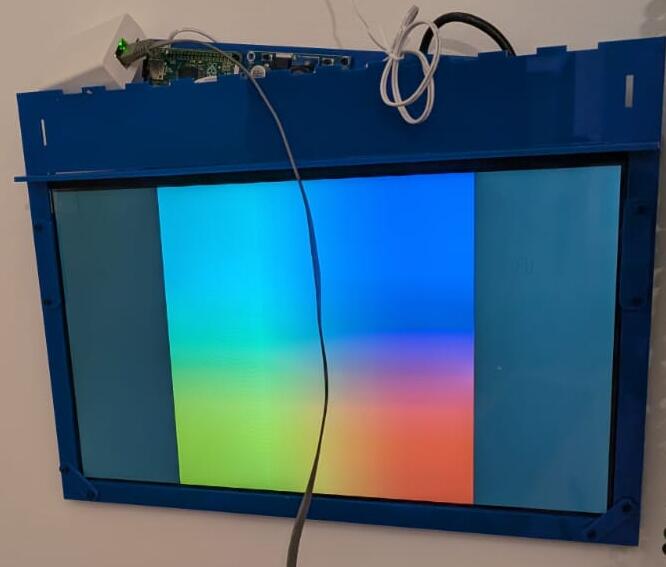
The 2 or 3 pixels above show the first "industrial design" of the homeboard. Or at least the parts that "work". It's hanging from a wall, like a real picture frame. Unfortunately it has bugs, and all its guts are hanging from the top.
I spent some time working on a mount, cut with a laser engraver. The mount has two main pieces: a frame for the display, and a horizontal mount that can be hanged from a hook in the wall. The vertical display frame slots into the horizontal mount, meaning there is no flimsy glue holding expensive equipment: gravity does the job. There are some screws and Ls to give it a nice shape, but the main stress between the hook in the wall and the display is supported by the material strength, not by glue. All the cool electronics fit in a small box on top of the horizontal mount. Or at least that's the idea.
As nice as my design is, it has bugs: You can see in the picture I forgot to consider that wires, especially fat cables such as HDMIs, have physical properties, such as bend radius. Without a slot for wiring, the electronics that fit nicely on the top box in my drawing, actually protrude from the top. The ribbon cable was mirrored in my drawing, meaning a weird 180-degree twist was needed to fit the screen to the main board. The box itself doesn't lock, because the "teeth" are slightly misaligned. And the screw holes for the Raspberry Pi are about a quarter mm out of alignment.
Attached to this post is my SVG design, with theoretical bug-fixes for the problems (version 3, if anyone is counting). I haven't tried printing it yet, and I wouldn't be surprised if V4 is required too.

Image above shows the outline; clicking on it should open the original svg, which is probably mostly blank because vector laser cuts have 0.001mm strokes. Download and open with Inkscape to see it (you may need to change the view mode to outline, too).
Bonus: misc Inkscape tips
My experience with anything that has colors is zero, and I had to spend time learning how Inkscape works to build the design above. Seeing a mechanical design you have in your head come to life with a laser cutter is incredibly rewarding, and I can see myself embarking in more ambitious designs some day, when I have more free time. Here's a list of things I learned and should remember next time I'm using Inkscape:
- It's easy to build complex shapes from basic ones using Path > Union/Difference/etc
- millimeter alignment is hard by hand, but using the position and size input boxes it becomes easy. Start all sub-assemblies in a new drawing, at (0,0), and follow the plans to build the full assembly.
- Actually, alignment by hand is easy (just not precise). It can be a time saver: Build guide-rules, then align by hand, finally adjust the position coordinates for precise fitting. For example, to place a screw hole in the bottom right corner, 3mm from the borders: the hard way is to calculate the position (width of board - 3mm - hole size / 2), same for height. The easy way: create a guide line at
width - 3mmandheight - 3mm. Place hole by hand, zooming in. The coordinates will usually be a few 100s or 10s of micrometers (um!) from the correct value, which you can then set by hand. - Actually, there's an even easier way: An element in inkscape will have 8 arrows around it. By default, the center of coordinates is the center of the object, but clicking on any of these arrows will make the coordinates relative to it. That means you can select the top center arrow of a screw hole, enter
board width - 3to position it horizontally, then select the left center arrow and enterboard height - 3to position it vertically. - When I write
board width - 3I actually mean you can writeNNN - XXXin the position boxes of Inkscape. They perform basic math operations. This is a huge time saver. - Most boards are regular, and have screw holes in symmetric positions vertically and horizontally. When this is the case, you can place all 4 screw holes by mirroring the first one: place the top left screw hole, then select it together with a box the size of the board. Mirror the board vertically, and place a new hole in the position of the first. Select both holes, mirror horizontally, etc. Voila, 4 screw holes with only one measurement!