 Nico Brailovsky's thought repository
Posts for 2025 February
Homeboard: eInk display
Post by Nico Brailovsky @ 2025-02-23 | Permalink | Leave a comment
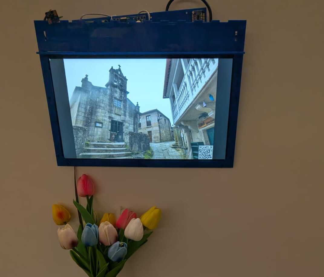
What's better than one display? Two displays, of course.
When I see a picture in my Homeboard, I often remember when and where I took it (photos are, after all, a form of exomemory), but not always. In wwwslide, my home slideshow service, I workaround this with a QR code: a small QR code is displayed in a corner of the image, and I can scan it to read the metadata of the picture being displayed. This is a good solution, but I'm not entirely happy with it.
Today, I added an eInk display to my Homeboard project. I can show picture metadata (and maybe even a QR code!) without taking up valuable picture real-estate. I chose an eInk display because they are easy to source and work with, relatively cheap, and require very little power (Homeboard is powered by PoE). Some day, I'm hoping to use it as an extra low-power mechanism to show actual homeboard info (a clock? weather? price of memecoins? The options are endless!)
I couldn't get all of the manufacturer's examples to work (especially the partial refresh), but it works well enough to display a thing rendered with Cairo. The original manufacturer's examples had a custom rendering library which was quite unnecessary; my version of lib-eInk gets rid of all the custom rendering code, and uses Cairo to create graphics. Here's an example:
struct EInkDisplay display = eink_init();
cairo_t cr = eink_get_cairo(display);
// Get display's surface
cairo_surface_t *surface = cairo_get_target(cr);
const size_t width = cairo_image_surface_get_width(surface);
const size_t height = cairo_image_surface_get_height(surface);
// Configure "pen"
cairo_set_source_rgba(cr, 0, 0, 0, 1);
cairo_select_font_face(cr, "Sans", CAIRO_FONT_SLANT_NORMAL, CAIRO_FONT_WEIGHT_BOLD);
cairo_set_font_size(cr, 20);
// Calculate text position
cairo_text_extents_t extents;
cairo_text_extents(cr, "Hola mundo", &extents);
double x = (width - extents.width) / 2 - extents.x_bearing;
double y = (height - extents.height) / 2 - extents.y_bearing;
// Draw
cairo_move_to(cr, x, y);
cairo_show_text(cr, text);
eink_render(display);
eink_delete(display);
Sidenote: my multiline code rendering seems to be eating pointers for breakfast, so struct S* may be rendered as struct S. I should fix this.
Homeboard V1, bootstrap V2
Post by Nico Brailovsky @ 2025-02-16 | Permalink | Leave a comment
With ~most~ some of the bugs fixed in the industrial design, it's time to setup a second Homeboard. That way I can experiment on one, while the other shows pretty pictures. Because my computer is also a new install, it's now a good opportunity to document the full bootstrap process from an almost brand new and clean Ubuntu 24.04.
Bootstrap a new devenv
- Get normal dev tools
sudo apt-get install build-essential git llvm vim - The linker needs to learn how to build arm binaries:
sudo apt-get install crossbuild-essential-armel crossbuild-essential-armhf - Clone the sw project:
git clone git@github.com:nicolasbrailo/homeboard.git - Don't forget to
git submodule update --init --recursive - Type
make xcompile-startin the root of gpio_mon. It will, on its first run, setup the cross-compile environment. - The x-compile env will be "hardcoded" to some rpi image, for example
2024-11-19-raspios-bookworm-armhf.img.xz. You probably want to update~/src/homeboard/pi_gpio_mon/rpiz-xcompile/mount_rpy_root.shto make it point to a newer image, ideally the same one you will use to bootstrap the sd card. - Once
make xcompile-startfinishes, you can check it succeeded;~/src/xcomp-rpiz-env/mntshould contain a copy of the rpi environment (the x-compile root)
Bootstrap the OS
This article has been updated to work, but the gist of it is:
- Find the ISO you used for the x-compile env, then
sudo dd of=/dev/sdX if=./XXXX.img bs=8M status=progress - Mount the SD card and enable ssh:
cd /media/$USER/bootfs && touch ssh && touch ssh.txt - Create user (headless):
echo username:password > /media/$USER/bootfs/userconf.txt - [Wayland] Add this magic to /boot/firmware/config.txt
dtoverlay=vc4-kms-v3d
gpu_mem=128
- [More Wayland] /boot/firmware/cmdline.txt needs to have
wayland=on - Boot up with the SD card, then ssh into the device and do
sudo apt-get install mesa-utils-bin wayfire seatd - Add Wayfire as a service
Build things
- Update the TARGET_IP in the makefile, then
make setup-sshto enable passwordless ssh - Start with the
gpio_monproject, it's the simplest.cd ~/src/homeboard/pi_gpio_mon. If youmake, it will either fail or create a binary in the wrong format if you haven't set up the cross-compile environment (see "bootstrap new devenv"). - After
makesucceeds,file gpiomonshould show something likeELF 32-bit LSB pie executable, ARM, EABI5 version 1 (SYSV), dynamically linked. This means your system can now build binaries for your target platform. scp gpiomon $target-> try out if your xcompile env works as expected
Build harder things
- Move on to
wl_display_toggle(it's the smallest project that exercises the entire stack: cross compiler and Wayfire). - There are more system deps you'll need to install;
make install_system_depsshould take care of most of them. - There are deps for the x-compile env too;
make install_sysroot_depsshould take care of most of them. Some deps may move around, and you may need to find newer versions. - Now
cd wl_display_togglethenmakeandscp wl_display_toggle $TARGET - ssh into the target, and try to shut off the display:
XDG_RUNTIME_DIR=/home/batman/run WAYLAND_DISPLAY="wayland-1" DISPLAY="" ./wl_display_toggle off
Install services
The homeboard doesn't do much nowadays, only show images; once you reached this point, and if things build and run, your build environment and target are ready to use. Just a few more arcane spells and we're done:
- Clean up binaries deployed ad-hoc, like gpio_mon and wl_display_toggle
make deploytgt- In the target, try out hackimg
- Run
XDG_RUNTIME_DIR=/home/batman/run WAYLAND_DISPLAY="wayland-1" DISPLAY="" /usr/lib/arm-linux-gnueabihf/ld-linux-armhf.so.3 /home/batman/homeboard/bin/hackimg /home/batman/homeboard/cfg/hackimg.cfg - You'll need to create the cache dir manually, because hackimg is lazy and won't do it for you
- Run
- Once you checked hackimg runs,
vi ~/homeboard/cfg/pipresencemon.cfg- Set the sensor pin to the GPIO acting as presence sensor
- Adapt the sensitivity to sensor type (mmwave vs PIR)
- It's recommendable to use the mock gpio for a test run
- Try out the ambience service
- In the target,
cd ~/homeboard/scripts && ./install_svc.sh- this will install the ambience service and launch it. Wayfire should already be a service by now, so no install is included. - Use
~/homeboard/scripts/logs.shto see what's broken.
The target should be ready for production, in only about 30 simple steps!
Appendix: it hangs!
Homeboard: Industrial Design (bonus: Inkscape)
Post by Nico Brailovsky @ 2025-02-09 | Permalink | Leave a comment
My Homeboard project has officially left its cardboard pizza phase. Almost:
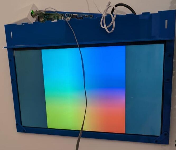
The 2 or 3 pixels above show the first "industrial design" of the homeboard. Or at least the parts that "work". It's hanging from a wall, like a real picture frame. Unfortunately it has bugs, and all its guts are hanging from the top.
I spent some time working on a mount, cut with a laser engraver. The mount has two main pieces: a frame for the display, and a horizontal mount that can be hanged from a hook in the wall. The vertical display frame slots into the horizontal mount, meaning there is no flimsy glue holding expensive equipment: gravity does the job. There are some screws and Ls to give it a nice shape, but the main stress between the hook in the wall and the display is supported by the material strength, not by glue. All the cool electronics fit in a small box on top of the horizontal mount. Or at least that's the idea.
As nice as my design is, it has bugs: You can see in the picture I forgot to consider that wires, especially fat cables such as HDMIs, have physical properties, such as bend radius. Without a slot for wiring, the electronics that fit nicely on the top box in my drawing, actually protrude from the top. The ribbon cable was mirrored in my drawing, meaning a weird 180-degree twist was needed to fit the screen to the main board. The box itself doesn't lock, because the "teeth" are slightly misaligned. And the screw holes for the Raspberry Pi are about a quarter mm out of alignment.
Attached to this post is my SVG design, with theoretical bug-fixes for the problems (version 3, if anyone is counting). I haven't tried printing it yet, and I wouldn't be surprised if V4 is required too.

Image above shows the outline; clicking on it should open the original svg, which is probably mostly blank because vector laser cuts have 0.001mm strokes. Download and open with Inkscape to see it (you may need to change the view mode to outline, too).
Bonus: misc Inkscape tips
My experience with anything that has colors is zero, and I had to spend time learning how Inkscape works to build the design above. Seeing a mechanical design you have in your head come to life with a laser cutter is incredibly rewarding, and I can see myself embarking in more ambitious designs some day, when I have more free time. Here's a list of things I learned and should remember next time I'm using Inkscape:
- It's easy to build complex shapes from basic ones using Path > Union/Difference/etc
- millimeter alignment is hard by hand, but using the position and size input boxes it becomes easy. Start all sub-assemblies in a new drawing, at (0,0), and follow the plans to build the full assembly.
- Actually, alignment by hand is easy (just not precise). It can be a time saver: Build guide-rules, then align by hand, finally adjust the position coordinates for precise fitting. For example, to place a screw hole in the bottom right corner, 3mm from the borders: the hard way is to calculate the position (width of board - 3mm - hole size / 2), same for height. The easy way: create a guide line at
width - 3mmandheight - 3mm. Place hole by hand, zooming in. The coordinates will usually be a few 100s or 10s of micrometers (um!) from the correct value, which you can then set by hand. - Actually, there's an even easier way: An element in inkscape will have 8 arrows around it. By default, the center of coordinates is the center of the object, but clicking on any of these arrows will make the coordinates relative to it. That means you can select the top center arrow of a screw hole, enter
board width - 3to position it horizontally, then select the left center arrow and enterboard height - 3to position it vertically. - When I write
board width - 3I actually mean you can writeNNN - XXXin the position boxes of Inkscape. They perform basic math operations. This is a huge time saver. - Most boards are regular, and have screw holes in symmetric positions vertically and horizontally. When this is the case, you can place all 4 screw holes by mirroring the first one: place the top left screw hole, then select it together with a box the size of the board. Mirror the board vertically, and place a new hole in the position of the first. Select both holes, mirror horizontally, etc. Voila, 4 screw holes with only one measurement!