Posts for 2024 June
Houseboard P0: PP0
Post by Nico Brailovsky @ 2024-06-30 | Permalink | Leave a comment
I have a ton of unnecessary home automation, but I'm lacking some kind of house board: a quick way of getting info before leaving (like weather, or transport conditions), leaving messages (don't forget to pick up kids from school) or just a shopping list. Sensible people would look at readily available digital signage solutions. Of course I didn't do that, instead decided to build my own.
I settled for a quick list of requirements to guide the project: Linux based, running off power-over-ethernet, with net-boot and 100% locally hosted. How hard can that be?
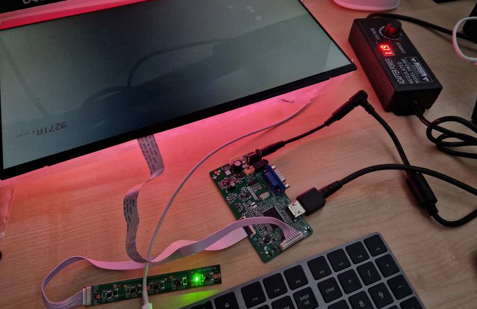
The first step to design my houseboard was searching for a panel. Here is a capture of the moment it failed:
Turns out that scoring a random replacement panel for a laptop and trying to pair that with a random controller board works well in theory but needs a lot of luck. Starting with a cheapish £40 LCD panel with an eDP connector, I got an HDMI-to-eDP board. My panel and my board didn't like each other, so all I got was backlight, and that is not very useful unless you only need to display binary information.
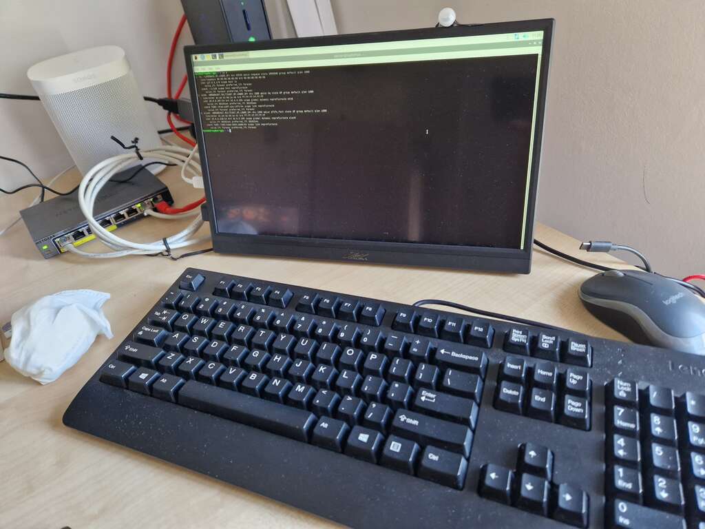
Since ordering and shipping a different panel controller board would take a few weeks, I decided to change my strategy: my P0 would be changed to a Prototype-Prototype-0 (PP0), using a similar platform to let me start working on the software and sensors, while I figured the way to control a panel. Here is Houseboard PP0, in all it's glory:
I got a USB-powered touchscreen, which is powered by a RaspberryPi 4. The RPI itself is powered over PoE, and there is an HDMI connection between the Rpi and the screen, and a secondary USB connection to get touch screen support. The PoE adapter is barely capable of powering the screen AND the Rpi: if I turn the brightness of the screen to 100%, the system will reset.
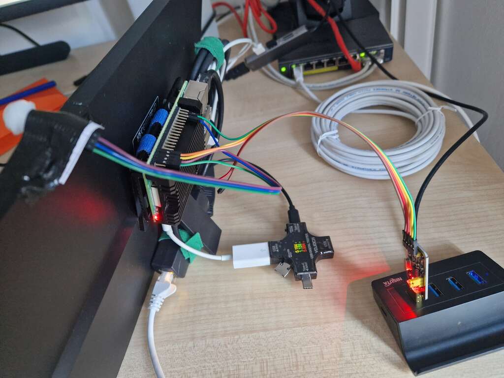
And with a few sensors (a PIR + mmWave):
It's not going to win any design prizes, but it works
While eventually I did end up solving my LCD panel woes, Houseboard PP0 let me start building some software for the houseboard quickly:
- A Wayland based image display built on top of Swayimage; to show a gallery of pictures when there is no other info to show
- A presence service (to determine when there are humans nearby, based on PIR and mmWave sensors).
BoM for Houseboard PP0
- A RaspberryPi 4 (any Pi will do, but having a bunch of USB ports makes this project a lot simpler)
- A USB powered screen. I went for a 14'' 1080p 1920x1080, and with the PoE constrain that's probably as big as it's feasible. My browsing history says I got this one: https://www.amazon.co.uk/dp/B0CB5FWGT8
- PoE splitter (USBC + ETH out, 5v 4A) - Look for the adapter with largest power rating you can, a cheap one won't work. I went for this one: https://www.amazon.co.uk/dp/B0CHW5K5F4
- PIR sensor (NB VCC=5v, connect to Pin4, GND Pin6, OUT Pin17)
- Smaller PIR sensor (VCC=5v Pin4, GND Pin6, OUT Pin17)
Useful references
RaspberryPi gpio cli monitor
Post by Nico Brailovsky @ 2024-06-15 | Permalink | Leave a comment
I wrote a small CLI utility to display when a GPIO pin changes state in a Raspberry Pi.
Using gpiomon, it's possible to monitor all pins to get an output like this:
$ ./gpiomon
CNT P00 P01 P02 P03 P04 P05 P06 P07 P08 P09 P10 P11 P12 P13 P14 P15 P16 P17 P18 P19 P20 P21 P22 P23 P24
000 >1< >1< >1< >1< >1< >1< >1< >1< >1<  0   0   0   0   0   0  >1<  0   0   0   0   0  >1<  0   0   0
001  1   1   1   1   1   1   1   1   1   0   0   0   0   0  >1<  1   0   0   0   0   0   1   0   0   0
002  1   1   1   1   1   1   1   1   1   0   0   0   0   0   1   1   0   0   0   0   0   1   0   0   0
003  1   1   1   1   1   1   1   1   1   0   0   0   0   0   1   1   0   0   0   0   0   1   0   0   0
004  1   1   1   1   1  >1<  1   1   1   0   0   0   0   0   1   1   0   0   0   0   0   1   0   0   0
005  1   1   1   1   1   1   1   1   1   0   0   0   0   0   1   1   0   0   0   0   0   1   0   0   0
Where the left most column is the number of seconds since startup. It's also easy to monitor a single pin:
$ ./gpiomon 21
000 PIN 21 = >1<
001 PIN 21 =  1
002 PIN 21 =  1
003 PIN 21 = >0<
004 PIN 21 =  0
005 PIN 21 =  0
006 PIN 21 = >1<
007 PIN 21 =  1
And most useful of all, an option to only print out (log) when a pin changes state. Eg:
$ ./gpiomon -u -l 21
000 PIN 21 = >1<
009 PIN 21 = >0<
015 PIN 21 = >1<
LD2410S: mmWave human-presence detection
Post by Nico Brailovsky @ 2024-06-15 | Permalink | Leave a comment
For a project, I bought a bunch of cheap LD2410S, an mmWave (radar) sensor to detect human presence (I actually started with an infrared sensor, but it had too many false negatives for my use case). The ones I got were pre-flashed with firmware to use a pin to announce presence or absence. To figure out if it's working or not, I tried using my GPIOmon byt found the sensor so accurate, that I couldn't manage to not detect my presence when in the room, no mater what material I used to cover it. Instead, I had to leave the room, and only then confirm the sensor was working as expected by looking at the GPIOmon logs.
The LD2410S also has a UART interface, and comes with a (Windows only) test app, but I wasn't able to make it work under Wine. I spent a bit of time reverse engineering how to talk UART with the LD2410S from the manual, and I got halfway there. There are examples, but many of them (even in the manufacturer's page) seem to be for a different model, and the LD2410S doesn't behave quite the same. First, I tested a basic command to figure out how to talk to the sensor:
import serial
import binascii
ser = serial.Serial('/dev/ttyUSB1', 115200, timeout=10)
def read_ser():
    data = b''
    while True:
        data = data + binascii.hexlify(ser.read())
        if data.endswith(b'04030201') or data.endswith(b'08070605') or len(data) > 50:
            print(' <= ', data)
            return
def ser_message(msg):
    head = "FDFCFBFA"
    tail = "04030201"
    fullmsg = head + msg + tail
    print(' => ', fullmsg)
    ser.write(binascii.unhexlify(fullmsg))
    read_ser()
# Enter config mode
ser_message("0400" + "FF000100")
# Request serial
ser_message("0200" + "1100")
# Write new serial
ser_message("0C00" + "10000800" + "BADB0B00F00DF00D")
# Request serial
ser_message("0200" + "1100")
# Disable config mode
ser_message("0400" + "FE010000")
ser.close()
If things work, the reply to the 4th message (request serial) should be the serial we set in the message just before. Something like <= b'fdfcfbfa0e00110100000800BADB0B00F00DF00D04030201'. Once that worked, I knew I could talk to the device over UART, but I still couldn't make sense of the periodic reports the device was sending:
import serial
import binascii
ser = serial.Serial('/dev/ttyUSB1', 115200, timeout=10)
data = b''
while True:
    data = data + binascii.hexlify(ser.read())
    if len(data) == 10:
        print('< ', data)
        data = b''
ser.close()
The periodic messages here didn't match any of the messages specified in the docs I found, so I printed these out together with the GPIO status. Got something like this:
<  b'6e02320162'    GPIO=1
<  b'6e02320162'    GPIO=1
<  b'6e00000062'    GPIO=0
<  b'6e00000062'    GPIO=0
...
<  b'6e00000062'    GPIO=0
<  b'6e01000062'    GPIO=0
<  b'6e01000062'    GPIO=0
<  b'6e02d20062'    GPIO=1
<  b'6e02d20062'    GPIO=1
<  b'6e02d20062'    GPIO=1
<  b'6e02d20062'    GPIO=1
I still haven't figured out what these messages mean, and my weekend timedout so it will have to wait (unless a kind reader of this note can drop me a line with info on how to parse the sensor's report, that is.)


