 Nico Brailovsky's thought repository
Posts for 2024 May
No cloud IoT: LAN only Security camera
Post by Nico Brailovsky @ 2024-05-23 | Permalink | Leave a comment
A while back I spent some time setting up a security camera/doorbell. I wanted to have a camera that
- Requires no external vendor connection: I must be able to run it locally, forever, with or without Internet.
- I can monitor on real time, ideally with my phone.
- notifies me when the doorbell button is pressed (integrating with the Sonos speakers throughout my home).
- triggers an event when motion is detected, so I can integrate it with other systems.
- stores videos on a disk when there is motion, so I can review them later.
- will send me a message when I'm out of home and motion is detected.
The process required a lot of trial and error, guessing arcane commands from poor documentation or from random (often decade-old, unmaintained) open source projects. I figured I should document my setup.
tl;dr
This article ended up being a lot longer than I expected, so if you're here for the short version:
- Reolink makes cameras that are easy to integrate with and require no cloud
-
Here's an example of how to subscribe and process camera events, like motion detection or doorbell presses.
-
Any sane camera will stream over RTSP. Once you find the RTSP URL, you can test it with ffmepg:
ffmpeg -i $rtsp_url, -c:v copy -c:a copy $outpath -
I built a hacky galery for stored RTSP streams.
-
And also send copies of the video over Telegram
Sourcing a camera
I went for Reolink. After a lot of reading (and a few months of usage, now) it's a very good option in its price range (cheap). They seem to have a good range of cameras, and all the features I was looking for: LAN-first, streaming, motion events, power-over-ethernet and a decent enough admin interface. Besides a very good range of PTZ (pan-tilt-zoom) cams, they also have a PoE a doorbell, which closed the deal for me.
PoE, again: Can't recommend PoE enough: there's no Wifi fighting, and if things get wonky you just ask the switch to cycle the port. You probably already need to run a cable for power, so why not do it for eth instead, and get both in one?
I would love a camera with open source firmware, but I figured if I spent my time tinkering with cam firmware, I would have never actually got the time to integrate it with my IoT network - so maybe a project for the far off future, when I have finished absolutely everything else on my ToDo list. As it is, I decided it's an acceptable trade-off to have an untrusted closed-source firmware running in my network, placed in an isolated vlan without internet access (it's not the only untrusted device I run in my network, and I admit not all of them live in vlans...)
Talking to the camera
There is a protocol called "ONVIF". Wikipedia claims it hails from the dark ages of the late 2000's, and it has an XML based transport to prove it. ONVIF is meant to be a standard way to discover how an IP camera works, but, like most XML-based protocols turned out to be in practice, is extremely verbose, requires you to traverse countless schema definition files to understand it, and it's quite hard to parse. Of course most cameras I've seen seem to implement ONVIF either partially or with non-standard extensions, making the whole design idea around the XML schema quite pointless anyway.
Reolink cams also support an HTTP/Json REST-like API, which makes things a lot easier. The HTTP interface is simple to inspect and understand by looking at the admin page with a browser's dev tools. Unfortunately, not everything is exposed through their HTTP API, so a bit of ONVIF digging may be necessary. Most notably, in the version of the firmware I tried, it's not possible to configure the camera to talk back to a server when events happen - which is quite important if you intend to use it as a doorbell.
There is an open source project that translates most of the Reolink HTTP commands to python. This project makes it very easy to replicate the functionality of the admin interface, but with a Python API. This project should cover 99% of all basic usage. Using this project, you can do things like cam.doorbell_led to set up the LED state. Most importantly, it will take care of the login flow for you, which is quite tedious to implement using raw requests.
Getting the camera to talk back to us
Note the project I linked above is actually a fork. The original project exists pretty much solely to integrate with HomeAssistant, and it's not too ~~user~~developer-friendly if what you're looking for is a way to configure a camera to talk back to a server. Since my most important goal was to use a camera as a doorbell, the first requirement was getting some sort of notification when the doorbell button is pressed.
Reolink cams can announce events back to a URL (as simple as cam.subscribe(webhook_url)), but they will do so in an ONVIF format. There is a standalone example of how to subscribe to ONVIF notifications, and how to parse them, over here.
In the example above, there is a Flask server printing a Json version of the ONVIF message. For Reolink cams, it prints the state of the camera (either motion detected, or doorbell button pressed) in a human-friendly Json format. I found the latency to be less than a second for the doorbell press event. The motion detection events, and the AI people detection events, also seem to trigger with low latency, but you'll need to tweak the config to suite your environment; if there is lots of movement in your street, it can be quite noisy.
Streaming
Streaming is easy! Reolink has an RTSP link. RTSP is an UDP based protocol that will transport media from a streaming device to another (and you likely use it every day, whenever you make a VoIP call). It's also lightweight, relatively sane, and comes to us from the late 90's (I wonder what happened between the 90's and 10's that gave us XML based protocols).
The RTSP link will be something like rtsp://$user:$pass@$cam_ip:554/h264Preview_01_main, but it's easier to ask the camera. There are different stream URLs, depending on the camera model, supported codecs, etc, so a little bit of trial and error may be required.
To test an RTSP URL, VLC is 80% likely to work. I found it, however, quite hard to debug failures using VLC. There may be codec mismatches, missing libraries, connection failures, or other random problems - and VLC it would just say "nope". This is usually good enough for most users, there is not too much a "normal" user can do on an RTSP setup failure. We are, however, not normal, so we use ffmpeg:
ffmpeg -i $rtsp_url, -c:v copy -c:a copy $outpath
This magic ffmpeg incantation will connecto to an RTSP URL and copy the incoming audio and video streams to a file, without any re-encoding (by default ffmpeg will try to reencode and spend tons of cpu on it). If everything goes fine, you'll end up with an mpeg of your camera. If it doesn't, ffmpeg will usually print a developer friendly (ish) error message.
Of course once we found a working RTSP URL we wouldn't want to use ffmpeg just to check who's at the door. For that, I found Ojo works amazingly well. It's an RTSP viewer for Android, available in F-Droid and probably other app stores.
NVR-like service
If you can see an RTSP stream, you can also save to disk. In fact that's exactly what we did to test it, with ffmpeg. My custom Reolink integration has an ffmpeg helper; whenever motion is reported by the camera, it will save a copy of the RTSP stream to disk. This means:
- we rely on the camera to report movement, so there can be false positives, and false negatives. You'll need to figure out how well the camera motion detection algorithms work for you.
- by only recording when the camera reports movement, we save a ton of disk space and CPU: no need to record when 99% of the day there is no motion. I like keeping my electricity bill down.
- but we miss the first few seconds of movement. By the time the camera triggers a motion alert, the RTSP is set up, and we start recording, it's likely that more than a few seconds have passed.
I don't know if this is how real NVR services behave: my IoT network is built for fun, and since I have fun coding, I don't always spend a lot of time looking into already-built services. I didn't immediately find an open source NVR-like service that worked as I wanted, so I quickly hacked one based on ffmpeg and some hacky Flask to create a gallery for the stored videos.
Telegram integration
By now, I had a camera integrated into a system that
- I can monitor on real time, using RTSP
- notifies me when the doorbell button is pressed
- triggers an event when motion is detected
- stores videos on a disk when there is motion
I was only missing IM notifications. I used Telegram for this, with a custom built integration. The notifications will trigger first when motion is detected, and it will send a still frame of the camera stream. Once the motion stops, it will reencode the video in a format that Telegram likes, and send it over too:
ffmpeg -i $fpath -vf scale=640:360 -c:v libx264 -crf 23 -preset veryfast -c:a copy $out_path
Unfortunately this integration seems to trigger some spam control in Telegram, and got my account banned. I recommend sending pictures only, that seems to be more acceptable to Telegram's term of service.
Raspberry Pi UART debug notes
Post by Nico Brailovsky @ 2024-05-19 | Permalink | Leave a comment
I spent a bit of time setting up UARTs to troubleshoot different Raspberry Pis. Here are my notes.
Electrical config
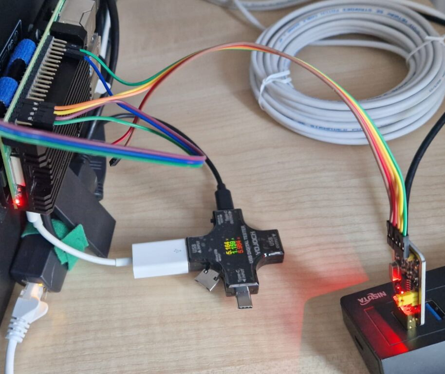
- Get a UART to USB adapter. I got one called "UART-TTL USB Adapter with CH340G Converter for 3.3 V" for less than $5. This one comes with 5 pins: 3.3v, 5v, tx, rx, gnd. For Rpi's UART, we'll ignore the two Vcc pins, we just need tx, rx and gnd. The adapter needs to run at 3.3v for an Rpi.
- Connect GND=Rpi pin 6, RX adapter = Rpi pin 8 (GPIO14/TXD), TX adapter = Rpi pin 10 (GPIO15/RXD). Remember that tx and rx need to be inverted: tx in the adapter should be plugged to rx in the Rpi - See here for a pinout map.
- UART is simple, but very sensitive to the quality of the electrical connection. Flaky connection leads to poor connectivity, and poor connectivity leads to lost bits. Really bad connections will come out garbled and impossible to read (probably not resembling text). Bad-but-not-terrible connections will appear broken, but legible (eg with missing characters). If the connection is flaky, try a different ground pin in the RPI (for example, you can switch GND to pin 39). You can also try a different USB hub.
- The adapter I got has an LED light for the TX path, and another for the RX path. This is very helpful to figure out if the connection is good (a bad connection results in a dim LED, or in both LEDs lighting up). It also helps detect when TX/RX are swapped.
Raspberry Pi config
- echo "enable_uart=1" > /boot/firmware/config.txt (Or change in the sd card).
- In a (booted) Rpi:
rpi-eeprom-config, then setBOOT_UART=1- this may not work in Raspberry Pis Zeros. - Adding
uart_2ndstage=1in config.txt should help get bootloader logs. - Don't forget to configure the Kernel:
console=serial0,115200should be in your cmdline.txt (it's set by default nowadays). - If you are troubleshooting boot issues,
bootcode_delay=3andboot_delay=3should add 3 seconds of delay between bootloaders. - init_uart_baud can tweak UART speed, but shouldn't be needed unless your connection is very flaky and you can't fix it for some reason.
There are other things in config.txt that may or may not help. Here's mine:
enable_uart=1
dtparam=uart0=on
uart_2ndstage=1
hdmi_force_hotplug=1
config_hdmi_boost=4
bootcode_delay=3
boot_delay=3
Test run
- Connect the adapter before power on the target, to get boot logs. The adapter should appear as /dev/ttyUSB0 or similar (tail dmesg to confirm)
- Monitor UART with
sudo screen /dev/ttyUSB0 115200(115200 seems to be the default speed in Rpi, configured as a kernel param in cmdline.txt) - Exit screen with
C-A \ - If you don't like screen, minicom is nicer (scrollback works better with tmux, out of the box):
sudo minicom --device /dev/ttyUSB0 - Exit minicom with
C-A x
Extra tip: Unlike their bigger brothers, Raspberry Pi Zeros don't seem to want to boot up with no SD card in, not even to show a bootloader error.
Example
If everything worked well, you should see either boot logs (if the UART was connected before power on) or a login screen. Here's an example of the first few seconds of my Rpi booting:
Raspberry Pi Bootcode
Read File: config.txt, 987
Read File: start.elf, 2980544 (bytes)
Read File: fixup.dat, 7303 (bytes)
MESS:00:00:04.185459:0: brfs: File read: /mfs/sd/config.txt
MESS:00:00:04.190074:0: brfs: File read: 987 bytes
MESS:00:00:04.226963:0: HDMI0:EDID error reading EDID block 0 attempt 0
MESS:00:00:04.233130:0: HDMI0:EDID error reading EDID block 0 attempt 1
MESS:00:00:04.239466:0: HDMI0:EDID error reading EDID block 0 attempt 2
MESS:00:00:04.245803:0: HDMI0:EDID error reading EDID block 0 attempt 3
MESS:00:00:04.252140:0: HDMI0:EDID error reading EDID block 0 attempt 4
MESS:00:00:04.258477:0: HDMI0:EDID error reading EDID block 0 attempt 5
MESS:00:00:04.264814:0: HDMI0:EDID error reading EDID block 0 attempt 6
MESS:00:00:04.271150:0: HDMI0:EDID error reading EDID block 0 attempt 7
MESS:00:00:04.277487:0: HDMI0:EDID error reading EDID block 0 attempt 8
MESS:00:00:04.283824:0: HDMI0:EDID error reading EDID block 0 attempt 9
MESS:00:00:04.289919:0: HDMI0:EDID giving up on reading EDID block 0
MESS:00:00:04.302298:0: brfs: File read: /mfs/sd/config.txt
MESS:00:00:07.306971:0: gpioman: gpioman_get_pin_num: pin LEDS_PWR_OK not defined
MESS:00:00:07.809022:0: gpioman: gpioman_get_pin_num: pin LEDS_PWR_OK not defined
MESS:00:00:07.814848:0: *** Restart logging
MESS:00:00:07.818724:0: brfs: File read: 987 bytes
MESS:00:00:07.826906:0: hdmi: HDMI0:EDID error reading EDID block 0 attempt 0
MESS:00:00:07.833596:0: hdmi: HDMI0:EDID error reading EDID block 0 attempt 1
MESS:00:00:07.840454:0: hdmi: HDMI0:EDID error reading EDID block 0 attempt 2
MESS:00:00:07.847313:0: hdmi: HDMI0:EDID error reading EDID block 0 attempt 3
MESS:00:00:07.854170:0: hdmi: HDMI0:EDID error reading EDID block 0 attempt 4
MESS:00:00:07.861028:0: hdmi: HDMI0:EDID error reading EDID block 0 attempt 5
MESS:00:00:07.867886:0: hdmi: HDMI0:EDID error reading EDID block 0 attempt 6
MESS:00:00:07.874743:0: hdmi: HDMI0:EDID error reading EDID block 0 attempt 7
MESS:00:00:07.881600:0: hdmi: HDMI0:EDID error reading EDID block 0 attempt 8
MESS:00:00:07.888459:0: hdmi: HDMI0:EDID error reading EDID block 0 attempt 9
MESS:00:00:07.895074:0: hdmi: HDMI0:EDID giving up on reading EDID block 0
MESS:00:00:07.900979:0: hdmi: HDMI0:EDID error reading EDID block 0 attempt 0
MESS:00:00:07.908770:0: hdmi: HDMI0:EDID error reading EDID block 0 attempt 1
MESS:00:00:07.915629:0: hdmi: HDMI0:EDID error reading EDID block 0 attempt 2
MESS:00:00:07.922486:0: hdmi: HDMI0:EDID error reading EDID block 0 attempt 3
MESS:00:00:07.929344:0: hdmi: HDMI0:EDID error reading EDID block 0 attempt 4
MESS:00:00:07.936201:0: hdmi: HDMI0:EDID error reading EDID block 0 attempt 5
MESS:00:00:07.943060:0: hdmi: HDMI0:EDID error reading EDID block 0 attempt 6
MESS:00:00:07.949917:0: hdmi: HDMI0:EDID error reading EDID block 0 attempt 7
MESS:00:00:07.956775:0: hdmi: HDMI0:EDID error reading EDID block 0 attempt 8
MESS:00:00:07.963633:0: hdmi: HDMI0:EDID error reading EDID block 0 attempt 9
MESS:00:00:07.970248:0: hdmi: HDMI0:EDID giving up on reading EDID block 0
MESS:00:00:07.976078:0: gpioman: gpioman_get_pin_num: pin EMMC_ENABLE not defined
MESS:00:00:07.991589:0: HDMI0: hdmi_pixel_encoding: 162000000
MESS:00:00:08.621290:0: brfs: File read: /mfs/sd/initramfs
MESS:00:00:08.625085:0: Loaded 'initramfs' to 0x0 size 0x9f66d9
MESS:00:00:08.642498:0: initramfs loaded to 0x1b5f9000 (size 0x9f66d9)
MESS:00:00:08.656992:0: dtb_file 'bcm2708-rpi-zero-w.dtb'
MESS:00:00:08.660702:0: brfs: File read: 10446553 bytes
MESS:00:00:08.671327:0: brfs: File read: /mfs/sd/bcm2708-rpi-zero-w.dtb
MESS:00:00:08.676246:0: Loaded 'bcm2708-rpi-zero-w.dtb' to 0x100 size 0x7823
MESS:00:00:08.696709:0: brfs: File read: 30755 bytes
MESS:00:00:08.713197:0: brfs: File read: /mfs/sd/overlays/overlay_map.dtb
MESS:00:00:08.749553:0: brfs: File read: 5195 bytes
MESS:00:00:08.757160:0: brfs: File read: /mfs/sd/config.txt
MESS:00:00:08.761107:0: dtparam: audio=on
MESS:00:00:08.771124:0: brfs: File read: 987 bytes
MESS:00:00:08.793681:0: brfs: File read: /mfs/sd/overlays/vc4-kms-v3d.dtbo
MESS:00:00:08.844556:0: Loaded overlay 'vc4-kms-v3d'
MESS:00:00:08.848045:0: dtparam: act_led_trigger=actpwr
MESS:00:00:08.865089:0: dtparam: uart0=on
MESS:00:00:08.974561:0: brfs: File read: 2760 bytes
MESS:00:00:08.981941:0: brfs: File read: /mfs/sd/cmdline.txt
MESS:00:00:08.985916:0: Read command line from file 'cmdline.txt':
MESS:00:00:08.991800:0: 'console=serial0,115200 console=tty1 root=PARTUUID=5c64668e-02 rootfstype=ext4 fsck.repair=yes rootwait'
MESS:00:00:09.100396:0: brfs: File read: 103 bytes
MESS:00:00:09.520104:0: brfs: File read: /mfs/sd/kernel.img
MESS:00:00:09.523957:0: Loaded 'kernel.img' to 0x8000 size 0x6c3648
MESS:00:00:09.529958:0: Device tree loaded to 0x1b5f1300 (size 0x7cde)
MESS:00:00:09.536944:0: uart: Set PL011 baud rate to 103448.300000 Hz
MESS:00:00:09.543886:0: uart: Baud rate change done...
MESS:00:00:09.547298:0: uart: Baud rate[    0.000000] Booting Linux on physical CPU 0x0
[    0.000000] Linux version 6.6.20+rpt-rpi-v6 (debian-kernel@lists.debian.org) (gcc-12 (Raspbian 12.2.0-14+rpi1) 12.2.0, GNU ld (GNU Binutils for Raspbian) 2.40) #1 Raspbian 1:6.6.20-1+rpt1 (2024-03-07)
[    0.000000] CPU: ARMv6-compatible processor [410fb767] revision 7 (ARMv7), cr=00c5387d
[    0.000000] CPU: PIPT / VIPT nonaliasing data cache, VIPT nonaliasing instruction cache
[    0.000000] OF: fdt: Machine model: Raspberry Pi Zero W Rev 1.1
[    0.000000] random: crng init done
[    0.000000] Memory policy: Data cache writeback
[    0.000000] Reserved memory: created CMA memory pool at 0x0b400000, size 256 MiB
[    0.000000] OF: reserved mem: initialized node linux,cma, compatible id shared-dma-pool
[    0.000000] OF: reserved mem: 0x0b400000..0x1b3fffff (262144 KiB) map reusable linux,cma
[    0.000000] Zone ranges:
[    0.000000]   Normal   [mem 0x0000000000000000-0x000000001bffffff]
[    0.000000] Movable zone start for each node
[    0.000000] Early memory node ranges
[    0.000000]   node   0: [mem 0x0000000000000000-0x000000001bffffff]
[    0.000000] Initmem setup node 0 [mem 0x0000000000000000-0x000000001bffffff]
[    0.000000] Kernel command line: coherent_pool=1M 8250.nr_uarts=1 snd_bcm2835.enable_headphones=0 snd_bcm2835.enable_hdmi=1 snd_bcm2835.enable_hdmi=0  smsc95xx.macaddr=B8:27:EB:E1:0B:27 vc_mem.mem_bast
[    0.000000] Dentry cache hash table entries: 65536 (order: 6, 262144 bytes, linear)
[    0.000000] Inode-cache hash table entries: 32768 (order: 5, 131072 bytes, linear)
[    0.000000] Built 1 zonelists, mobility grouping on.  Total pages: 113680
[    0.000000] mem auto-init: stack:all(zero), heap alloc:off, heap free:off
[    0.000000] Memory: 165396K/458752K available (10000K kernel code, 1478K rwdata, 3116K rodata, 452K init, 582K bss, 31212K reserved, 262144K cma-reserved)
[    0.000000] SLUB: HWalign=32, Order=0-3, MinObjects=0, CPUs=1, Nodes=1
[    0.000000] ftrace: allocating 34944 entries in 103 pages
[    0.000000] ftrace: allocated 103 pages with 5 groups
[    0.000000] trace event string verifier disabled
[    0.000000] NR_IRQS: 16, nr_irqs: 16, preallocated irqs: 16
[    0.000006] sched_clock: 32 bits at 1000kHz, resolution 1000ns, wraps every 2147483647500ns
[    0.000061] clocksource: timer: mask: 0xffffffff max_cycles: 0xffffffff, max_idle_ns: 1911260446275 ns
[    0.000146] bcm2835: system timer (irq = 27)
[    0.000913] Console: colour dummy device 80x30
[    0.000949] printk: console [tty1] enabled
[    0.001662] Calibrating delay loop... 697.95 BogoMIPS (lpj=3489792)
[    0.060283] CPU: Testing write buffer coherency: ok
[    0.060386] pid_max: default: 32768 minimum: 301
[    0.060548] LSM: initializing lsm=capability,integrity
[    0.060859] Mount-cache hash table entries: 1024 (order: 0, 4096 bytes, linear)
[    0.060931] Mountpoint-cache hash table entries: 1024 (order: 0, 4096 bytes, linear)
[    0.062179] cgroup: Disabling memory control group subsystem
[    0.064297] RCU Tasks Rude: Setting shift to 0 and lim to 1 rcu_task_cb_adjust=1.
[    0.064590] RCU Tasks Trace: Setting shift to 0 and lim to 1 rcu_task_cb_adjust=1.
[    0.064902] Setting up static identity map for 0x8220 - 0x8258
[    0.066193] devtmpfs: initialized
[    0.078200] VFP support v0.3: implementor 41 architecture 1 part 20 variant b rev 5
[    0.078605] clocksource: jiffies: mask: 0xffffffff max_cycles: 0xffffffff, max_idle_ns: 19112604462750000 ns
[    0.078696] futex hash table entries: 256 (order: -1, 3072 bytes, linear)
Won't win any ID prizes, but it got the job done:
Raspberry Pi: HDMI debugging
Post by Nico Brailovsky @ 2024-05-18 | Permalink | Leave a comment
If a Raspberry Pi boots but has no HDMI signal:
- Add
hdmi_force_hotplug=1to /boot/firmware/config.txt - this forces the Pi to send HDMI video even if it thinks there's no monitor connected. - Add
config_hdmi_boost=4to /boot/firmware/config.txt - this tweaks the HDMI signal strength.
Also, remove all possible adapters (each will add a bit of noise and attenuation) and get a cable with good shielding.
Source https://elinux.org/R-Pi_Troubleshooting#No_HDMI_output_at_all
Extra tip: Unlike their bigger brothers, Raspberry Pi Zeros don't seem to want to boot up with no SD card in, not even to show a bootloader error.
Zigbee Boiler
Post by Nico Brailovsky @ 2024-05-06 | Permalink | Leave a comment
Weekend project: made my boiler Zigbee compatible, bypassing a Drayton heating thermostat. I'm quite proud of the final results:
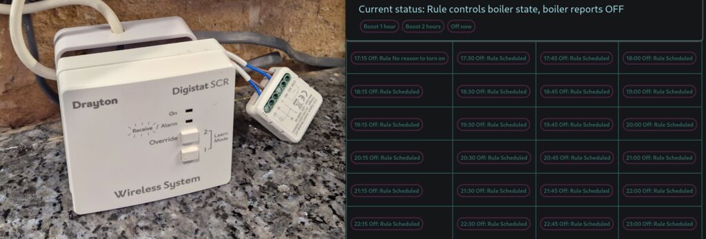
On the left, the wiring; on the right, the control panel. Disclaimer: this note shows an experiment. Don't take any electrical advise from this text.
For a few years, I've been using my own home automation system, developed almost from scratch. I should write about it some day (tl;dr, it was a fun weekend project that turned into multiple, mostly fun, weekend projects). Something missing from my home automation was heating integration, which is especially sad given I have Zigbee temperature sensors everywhere. With the winter over I spent a weekend working on making my boiler Zigbee compatible (wouldn't want an expensive emergency visit in the middle of winter to repair my boiler).
My boiler uses a Drayton thermostat as a control, which seems very common in the UK (n=3). They seem mostly used as an on/off switch (OpenTherm isn't very common here), so there's no reason I couldn't bypass it with a relay while keeping the normal thermostat as a backup. Both the installation manual and the back of my control unit confirm this:
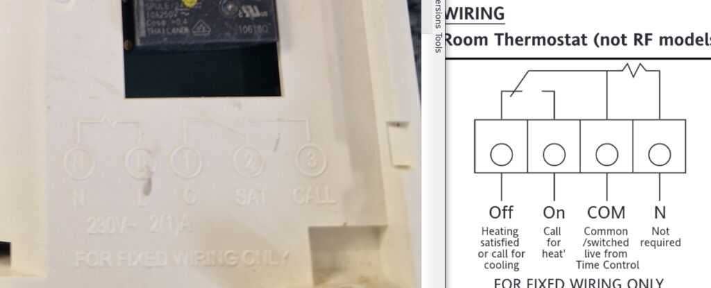
The heating-on signal is just closing the circuit between two terminals. For good measure, I decided to check this with a volt-meter (which, by the way, I strongly recommend against; unlike attaching a probe to a running program with gdb, probing a live circuit can be a shocking experience).
Once I was triple sure the chances of sparks and magic smoke where low, I got a 1 channel Zigbee relay module (220v, dry, 5 amps); if you are reading this guide for inspiration, make sure your switch can handle more power than your fuse. You don't want random electrical equipment acting as a fuse for your fuse. Also look for a "dry" relay, to keep power supply and control circuits separate, and needless to say it should handle 220V. I went for a "MHCOZY Tuya Dry Contact Zigbee Relay Switch Module,1 Channel AC 100-240V" - there are a few like these and they all seem to be the same whitelabel Zigbee element.
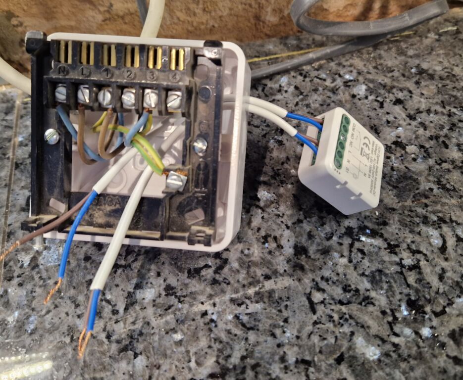
A picture of the wiring; the connection needs to be parallel to the existing controller, to keep both working.
The control logic lives in my monolithic home automation repo, as a set of configurable Python rules, and while I've only had a few cold days to try them out, they seem to work. Next winter I'll be able to control my thermostat remotely from my Telegram bot, while I take a holiday to the beach.